Flying Command Posts
 The aviation forces of the GSFG were equipped with two other special variants of the Mi-6A.
The first was designated Mi-6A VKP (VKP for Vozdushnyy Kommandnyy Punkt or Airborne Command Post) or "Product" izd.50A VKP.
Designated "Hook-B" by NATO, it was developed on the basis from the series-produced Mi-6A especially by the Equipment
Management Branch (ORO) at the 535th VVS Repair Plant in Konotop. Work on the first helicopter started in late 1972 and 36 new-built "Hooks" were finally transformed into Mi-6VKP at that plant.
The helicopter was designed for combat control of the troops of a combined arms army or air army.
Such helicopters were used among others to ensure uninterrupted command and control of units on the move, create new communication channels unknown to the enemy,
coordinate the preparation of a tactical nuclear strike or replace a destroyed ground command post.
The aviation forces of the GSFG were equipped with two other special variants of the Mi-6A.
The first was designated Mi-6A VKP (VKP for Vozdushnyy Kommandnyy Punkt or Airborne Command Post) or "Product" izd.50A VKP.
Designated "Hook-B" by NATO, it was developed on the basis from the series-produced Mi-6A especially by the Equipment
Management Branch (ORO) at the 535th VVS Repair Plant in Konotop. Work on the first helicopter started in late 1972 and 36 new-built "Hooks" were finally transformed into Mi-6VKP at that plant.
The helicopter was designed for combat control of the troops of a combined arms army or air army.
Such helicopters were used among others to ensure uninterrupted command and control of units on the move, create new communication channels unknown to the enemy,
coordinate the preparation of a tactical nuclear strike or replace a destroyed ground command post.
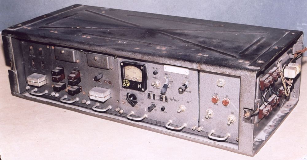
The "Hook-B" were not equipped with a specific communication suite; however, they carried the following communications equipments
(> Link):
 - 3 R-111 wide band HF complete radio sets (1) to communicate with ground troops >
Link.
- 1 R-130 HF complete radio set (inflight relay for R-140 radios) >
Link 1 /
Link 2.
- 1 R-140 HF complete radio set usable only on the ground with an external antenna
deployed (R-155 receiver) > Link.
- 1 R-409 VHF complete radio-relay set usable in flight or on the ground with an
external antenna deployed > Link 1 /
Link 2.
- 2 R-802VYa VHF complete aviation radio sets > Link.
- 1 or 2 R-831M1 mid-range VHF complete aviation radio sets > Link.
- 1 R-847 complete telephony and radiotelegraphy short wave air radio set (R-846
receiver) >
Link.
- 1 P-303 Topaz communication channel compressor for the R-409 radio (compression of radio relay lines with allocation
of up to
three telephone channels in each direction of transmission of the main line) >
Link.
- 1 P-317 communication channel compressor for the R-409 radio
(compresses one communication channel in telephone mode with
a telegraph channel while maintaining the main telephone channel) >
Link.
 On some transmitters, several channels could be connected simultaneously on a single frequency (multiplexing or teleconferencing).
The helicopter also was equipped with a SRO-2M Khrom-Nikel IFF system, ensuring its identification by friendly forces.
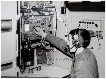
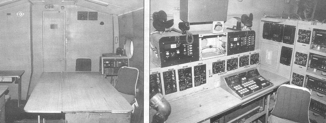
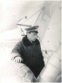
Beside the regular crew of six, three radio operators and two officers were seated in the front part of the cargo compartment, while a bulkhead separated the rear section called
the "salon" where command and control officers were accomodated
>
Photo. Finally, a storage compartment and some electronic equipment were located behind another bulkhead.
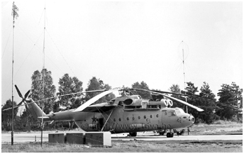
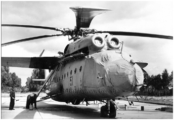
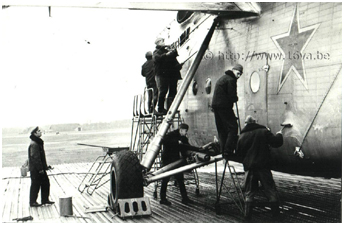
Most publications mention that the Mi-6VKP could only perform its mission on the ground, when various additional antennas were deployed outside the helicopter.
Two telescopic masts usually were attached horizontally to the lateral supports of the main
landing gear struts on each side of the fuselage during flight. Once the helicopter had landed in an operational area, they were removed and deployed
on the field with antennas attached at their top. It has been reported that they could reach up to 19.5 meters high.
Also, three folding brackets to hold an antenna were attached to the fuselage behind the left front side door. Two plugs to connect
antenna cables were also available on the fuselage side in the same area.
However, the "Hook-B" most probably also was able to operate in flight. The efficiency of some of the antennas mounted on the tail boom (description below)
would have been poor on the ground.
The electric system of the helicopter had been upgraded to supply power to multiple radios, but it was the standard AI-8 APU of the Mi-6A that
powered them on the ground. The endurance during flight operations was limited by storage battery capacity.
On some transmitters, several channels could be connected simultaneously on a single frequency (multiplexing or teleconferencing).
The helicopter also was equipped with a SRO-2M Khrom-Nikel IFF system, ensuring its identification by friendly forces.
Beside the regular crew of six, three radio operators and two officers were seated in the front part of the cargo compartment, while a bulkhead separated the rear section called
the "salon" where command and control officers were accomodated
>
Photo. Finally, a storage compartment and some electronic equipment were located behind another bulkhead.
Most publications mention that the Mi-6VKP could only perform its mission on the ground, when various additional antennas were deployed outside the helicopter.
Two telescopic masts usually were attached horizontally to the lateral supports of the main
landing gear struts on each side of the fuselage during flight. Once the helicopter had landed in an operational area, they were removed and deployed
on the field with antennas attached at their top. It has been reported that they could reach up to 19.5 meters high.
Also, three folding brackets to hold an antenna were attached to the fuselage behind the left front side door. Two plugs to connect
antenna cables were also available on the fuselage side in the same area.
However, the "Hook-B" most probably also was able to operate in flight. The efficiency of some of the antennas mounted on the tail boom (description below)
would have been poor on the ground.
The electric system of the helicopter had been upgraded to supply power to multiple radios, but it was the standard AI-8 APU of the Mi-6A that
powered them on the ground. The endurance during flight operations was limited by storage battery capacity.
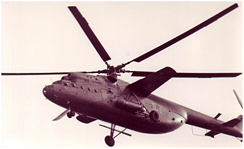
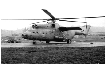
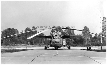
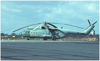
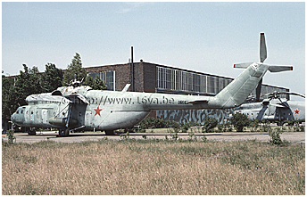
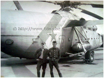
 This type of "Hook" could be identified by the four large blade antennas mounted around the rear of the tail boom in front of the horizontal stabilizers
(the shape and the number of antennas could vary depending on the equipment carried) and by the large U-shaped tubular antenna placed under the tail boom
> Photo.
Wire antennas also were stretched on the fuselage sides > Photo.
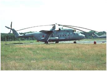
Most of the time, the external self-sealing fuel tank on the starboard side was not mounted. However, a large fairing with an air intake
was located in front of the usual location of that tank. It was a KO-50 kerosene heater (the same as on the starboard side of the Mi-8 and the Mi-10K)
intended for heating the "salon" compartment and the helicopter's equipment in winter. The Mi-6s heating and ventilation system was indeed insufficient,
even for the pilots themselves.
The Mi-6VKP photographed in the GDR all seemed to be equipped with the KO-50; however, it was not the case for the entire "Hook-B" fleet.
A small fuel tank whose exact function remains to be discovered, was attached outside the rear starboard fuselage.
A red rectangular band sometimes was painted behind and above this tank (> Photo).
It was a remnant of old standard markings that apparently were only rarely painted (see this manual
> Link). Bort numbers 50 (> Photo) and 53 in the 113.OSAE had that red band.
A dozen of Mi-6VKP were spread among the separate combat and control squadrons (OVE BU) - one or two per unit - that were assigned to the five Soviet ground armies and the 16.VA in the GDR.
This type of "Hook" could be identified by the four large blade antennas mounted around the rear of the tail boom in front of the horizontal stabilizers
(the shape and the number of antennas could vary depending on the equipment carried) and by the large U-shaped tubular antenna placed under the tail boom
> Photo.
Wire antennas also were stretched on the fuselage sides > Photo.
Most of the time, the external self-sealing fuel tank on the starboard side was not mounted. However, a large fairing with an air intake
was located in front of the usual location of that tank. It was a KO-50 kerosene heater (the same as on the starboard side of the Mi-8 and the Mi-10K)
intended for heating the "salon" compartment and the helicopter's equipment in winter. The Mi-6s heating and ventilation system was indeed insufficient,
even for the pilots themselves.
The Mi-6VKP photographed in the GDR all seemed to be equipped with the KO-50; however, it was not the case for the entire "Hook-B" fleet.
A small fuel tank whose exact function remains to be discovered, was attached outside the rear starboard fuselage.
A red rectangular band sometimes was painted behind and above this tank (> Photo).
It was a remnant of old standard markings that apparently were only rarely painted (see this manual
> Link). Bort numbers 50 (> Photo) and 53 in the 113.OSAE had that red band.
A dozen of Mi-6VKP were spread among the separate combat and control squadrons (OVE BU) - one or two per unit - that were assigned to the five Soviet ground armies and the 16.VA in the GDR.
 The second special "Hook" variant present in East Germany was the Mil' Design Bureau's Article 50AYa or Mi-6AYa (Ya for Yakhont or Ruby - the onboard radio and associated
system suite), also designated Mi-6VzPU (VzPU for Vozdushnyy Punkt Upravleniya - airborne control post) and sometimes called
Mi-6BUS (Bortovyye Uzly Svyazi - onboard communications nodes).
The first helicopters built by the Rostov Helicopter Plant were introduced into service in 1975 under their Mi-22 military designation, or "Hook-C" for the West.
The Mi-22 was designed for combat control of the troops of a combined arms army as was the case for the "Hook-B" and it was able to fulfill its mission both in flight and from the ground.
The Yakhont communication suite improved systems management and automation while simultaneously using more communication channels
(> Photo).
Electronics were partially using semiconductors on this model.
The IFF system of the Mi-22 was a Parol'.
The second special "Hook" variant present in East Germany was the Mil' Design Bureau's Article 50AYa or Mi-6AYa (Ya for Yakhont or Ruby - the onboard radio and associated
system suite), also designated Mi-6VzPU (VzPU for Vozdushnyy Punkt Upravleniya - airborne control post) and sometimes called
Mi-6BUS (Bortovyye Uzly Svyazi - onboard communications nodes).
The first helicopters built by the Rostov Helicopter Plant were introduced into service in 1975 under their Mi-22 military designation, or "Hook-C" for the West.
The Mi-22 was designed for combat control of the troops of a combined arms army as was the case for the "Hook-B" and it was able to fulfill its mission both in flight and from the ground.
The Yakhont communication suite improved systems management and automation while simultaneously using more communication channels
(> Photo).
Electronics were partially using semiconductors on this model.
The IFF system of the Mi-22 was a Parol'.
The "Hook-C" carried the following radio sets:
 - 3 R-111 wide band HF half-radio sets (1) to communicate with ground troops
Link.
- 3 R-409 VHF complete half-radio-relay sets usable in flight or on the ground with an
external antenna deployed > Link 1 /
Link 2.
- 1 R-802VYa VHF complete aviation radio set > Link.
- 1 R-831M1 mid-range VHF complete aviation radio set > Link.
- 1 R-856 complete aviation radio set
- 1 R-857 complete aviation radio set
- 1 R-886 complete aviation radio set
- 1 P-303 "Topaz" communication channel compressor for the R-409 radio
(compression of radio relay lines with allocation
of up to three telephone channels in
each direction of transmission of the main line) >
Link.
- 1 P-317 communication channel compressor for the R-409 radio
(compresses one communication channel in telephone mode with
a telegraph channel while maintaining the main telephone channel) >
Link.
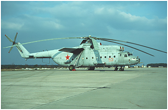
 The "Hook-C" antennas were less conspicuous. The major external identifying feature of
a Mi-22 was the big blade antenna attached on top of the rear fuselage. Several smaller antennas were also protruding under the fuselage.
The Mi-22 was also used as a ground command post: two short masts and a longer one were carried left and right, respectively, of the fuselage
attached to the landing gear struts. This Mi-6A derivative was not equipped with an AI-8 APU. Instead, a TA-6 auxiliary power unit was mounted on the inside face
of the right clam-shell door. This auxiliary turbine that also equipped such aircraft as the Il-76 or the Tu-154, could provide electric power to the communication
equipment while in flight and when on the ground.
The performance of the built-in air conditioning system was increased due to the need to heat the salon and special equipment installation areas.
Consequently, the Mi-22 had no KO-50 kerosene heater and the standard fuel tank was mounted on the right side of the fuselage.
Like with the Mi-6VKP, a red band sometimes was painted on the right side of the rear fuselage > Photo.
The few "Hook-C" seen in East Germany were deployed alongside the Mi-6VKP in the same units because each helicopter type had its specificities.
The "Hook-C" antennas were less conspicuous. The major external identifying feature of
a Mi-22 was the big blade antenna attached on top of the rear fuselage. Several smaller antennas were also protruding under the fuselage.
The Mi-22 was also used as a ground command post: two short masts and a longer one were carried left and right, respectively, of the fuselage
attached to the landing gear struts. This Mi-6A derivative was not equipped with an AI-8 APU. Instead, a TA-6 auxiliary power unit was mounted on the inside face
of the right clam-shell door. This auxiliary turbine that also equipped such aircraft as the Il-76 or the Tu-154, could provide electric power to the communication
equipment while in flight and when on the ground.
The performance of the built-in air conditioning system was increased due to the need to heat the salon and special equipment installation areas.
Consequently, the Mi-22 had no KO-50 kerosene heater and the standard fuel tank was mounted on the right side of the fuselage.
Like with the Mi-6VKP, a red band sometimes was painted on the right side of the rear fuselage > Photo.
The few "Hook-C" seen in East Germany were deployed alongside the Mi-6VKP in the same units because each helicopter type had its specificities.
| "Hook-B" and "Hook-C" in the GDR / late 1980s - early 1990s |
 Let's attempt to explain the plethora of designations relative to the flying command posts. These helicopters included a command compartment (VzPU or VKP) and one
or more communication nodes (BUS), which explains these different ways of designating a single helicopter. These terms were therefore not specific to a precise type of onboard hardware such
as an "X" communication suite.
Let's attempt to explain the plethora of designations relative to the flying command posts. These helicopters included a command compartment (VzPU or VKP) and one
or more communication nodes (BUS), which explains these different ways of designating a single helicopter. These terms were therefore not specific to a precise type of onboard hardware such
as an "X" communication suite.
Epilogue
While the successor to the Mi-6 had been flying since the early 1980s, production and delivery of the Mi-26 took place at a slow pace and in limited quantities
(only 150 machines would have been added to the inventory). Oranienburg was chosen to be the first overseas base where this new helicopter model was to be deployed permanently.
Personnel assigned to the 239.OGVP would have been advised of this future upgrade to the Mi-26 in the early 1990s, and that unit conversion was imminent.
Ultimately only a dozen
"Halo" were be assigned to 16.VA HQ to replace the Mi-6s; the performance and payload capabilities of the new machine largely compensated for the greatly reduced number of helicopters.
The Soviet Union's collapse and the withdrawal of the 239.OGVP from Germany put an end to this project (information taken from "Beginning of the end" by Stefan Büttner, published in the
November 2009 issue of "Aircraft").
With special thanks to Valeriy Belichenko for his unstinting help.
| Mi-6 PHOTO PAGE |
notes
(1) The concept of a complete radio set generally involved the presence of two identical radios, while a half-set consisted of a single radio. A half-set could only work in one direction, while a complete set worked in two directions or could act as a relay. A single-channel system consisting of two half-sets could operate in duplex mode. Multi-channel half-sets operated in two directions or in relay mode.
 |
The Mi-6 & Mi-10 < Part 1 |
| Plan du site - Sitemap |